Some devices need more than a standard Test Reset sequence to enter the state when they behave as described in their BSDL file and boundary scan can run. Infineon’s Aurix TriCore TC3xx microcontroller family is one such group.
Without additional instructions being sent to the device during the Test Reset sequence, it may be impossible to scan data through the boundary scan register in SAMPLE and EXTEST modes, even though the device’s ID code can be read and the instruction register scanned.
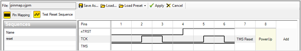
To put a TC3xx device correctly into boundary scan mode, an internal register needs to be configured after power-cycling the board with the Test Reset pin held low and applying two TMS Resets.
This can be done by creating a Circuit Code file containing the following code (for a device named U1 with a Test Reset signal defined as nTRST in the XJLink2’s pin mapping). A Test Reset sequence can then be used to call the PowerUp()() function. Change the name of the constant from “U1” to match your circuit.
GLOBAL INT FIRST_POWER_UP := TRUE;
LOCAL CONST INT IO_PATH := 0b11000000;
CONST STRING DEVICE_TO_INIT := "U1"; //change to match your circuit

//N.B. this code assumes the nTRST pin controlling DEVICE_TO_INIT is called nTRST in the pin mapping
PowerUp()()
  INT key;
  JTAG
    IF FIRST_POWER_UP THEN
      SET PIO.nTRST := 0;

      SLEEP(100);

      PRINT("Power cycle the board and then press a key to continue\n");
      key := WAITKEY();
    END;

    SET PIO.nTRST := I;

    FIRST_POWER_UP := FALSE;

    // TMS Reset
    INJTAGSTATE "DRPAUSE";
    JTAGSTATE "RESET";
    SLEEP(100);

    // TMS Reset
    INJTAGSTATE "DRPAUSE";
    JTAGSTATE "RESET";

    IR DEVICE_TO_INIT WIDTH 8 := IO_PATH;
    IRSCAN "IDLE";

    DR DEVICE_TO_INIT WIDTH 3 := 0;
    DRSCAN "IDLE";

    IR DEVICE_TO_INIT := "IDCODE";
    IRSCAN "IDLE";
  END;
END;
If the JTAG chain includes other devices that require special Test Reset sequences, additional code may be required to accommodate them.
A simple Test Reset sequence that calls the above function from your Circuit Code file would look similar to this:
Leave A Comment